
Introduction
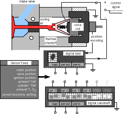
A digital camshaft
is an electronically controlled valve modulation device that replaces a
conventional mechanical camshaft. A digital camshaft has several
advantages over a conventional camshaft. One advantage is that the
lobe shape of the digital cam can be varied as a function of engine speed
and combustion conditions. This is difficult to accomplish with a
conventional mechanical camshaft. A second advantage is that individual
lobe offset (valve timing) can be varied in relation to ignition timing
and crank position in real time. A third advantage is a possible
reduction in power dissipation compared to mechanical camshafts.
A disadvantage is an increase in system complexity. Because this
complexity is electronic rather than mechanical, it is more easily managed.
Note that in the general case lobe offset is a subset of lobe shape.
Open issues are those of how to factor the logic and power activation capability,
on a per lobe, per cylinder or per camshaft basis. A per cylinder
approach is proposed here since any chipware developed as part of the prototyping
activity could be instanced for different engine configurations without
incurring significant additional development costs.
For the purposes of this analysis, it will be assumed that the successful modulation of valve position via a digitally controlled, position encoding, solenoidal system is possible. If successful this approach is applicable to all four cycle internal combustion engines. We will now ask a set of questions whose purpose is to assess an appropriate first context for this technology. Prototyping of this technology is best done in a single cylinder context. Per cylinder chipware can be reused.
On a more general line of reasoning it is interesting to consider how much this technology - if it were deployed - could influence engine design. Consider the a design variable as elementary as the optimal number of cylinders:
Question 1: If we employ a digital camshaft, and if the frictional losses of that digital camshaft are significantly less than those of a conventional camshaft, how many cylinders should the engine have? This leads to a second question.
Question 2: To first order, how do internal frictional losses vary as the number of cylinders is increased from one cylinder to more than one?
Answer: For a "square" engine where bore equals stroke, we seek a relation between contact area (friction) and enclosed volume (power) as the number of cylinders increases. We will assume that, in the presence of a digital camshaft, cylinder wall losses account for the majority of the internal frictional losses in an internal combustion engine. The result is:
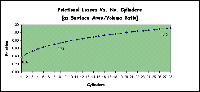
If frictional wall contact losses were a principal design driver, then all engines would have only one cylinder. This is not the case. There is also the issue of engine smoothness. We know that as we increase the number of cylinders in an internal combustion engine, the engine runs more smoothly. This depends on a number of design variables, flat opposed configurations, V configurations and inline configurations and firing order. We will defer evaluating these design variables for the moment and focus on cylinder count alone.
Question 3: To first order, how does engine smoothness vary as the number of cylinders is increases from one to more than one. The result is:
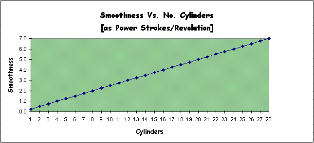
Question 4: Quality per Unit Cost. If we take the engineering virtue of smoothness, (large values are good) and multiply it by the reciprocal of losses (large values are good) we can define a notion of quality. We can then ask at how quality varies with cost, where the cost metric is engine complexity. Engine complexity is measured as parts count where each part has some characteristic MTBF - Mean Time Before Failure. A plot of quality versus cost looks like:
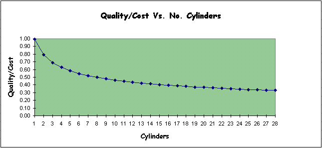
From this plot we see that an eight cylinder engine is twice as expensive to field as a one cylinder engine all things being equal, assuming our simplifying assumptions are met.
Question 5: Is there a weight advantage that accrues from having more or fewer cylinders. That is, which is lighter for a given displacement, a single cylinder engine or one with many cylinders? The answer is, to first order:
Valve Aspects
With this kind of
approach the compression forces on the valve stem are presumably less than
with a conventional camshaft. There is a necessity to keep heat from
being transferred to the solenoid or position encoder sections. Magnetic
materials with high flux density tend to be quite temperature sensitive
and must be kept below their demagnetization or "Curie" point. Optical
position encoders can be more robust, but their semiconductors must be
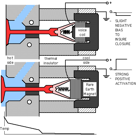
appropriately protected. The diagrams above show this being accomplished
via both a thermal standoff (distance) and cooling air (convection). The
lower axial forces and cooler running requirements suggests a hollow stem
of a possibly non-metallic reinforced ceramic material. Engine RPM
is typically limited by valve train performance, e.g. "valve float".
This mandates as light a valve as possible. Since maximum excursion
frequency is limited by the mass of the valve there is an additional driver
for keeping the valve as light as possible. A reinforced or directionally
solidified ceramic valve with a metallic seal might serve as an appropriate
alternative. Since the heaviest component of the digital camshaft
lobe is a rare earth magnet, it might be possible to have the digital camshaft
and valve train weigh less than conventional camshafts and valve trains
resulting in a saving of weight. Heat dissipation requirements suggest
that the footprint of the system will be about the same size or slightly
larger than conventional valve trains.
Solenoid Activation
Driving the valves
is very similar to driving a conventional loudspeaker with a couple of
exceptions. Although the signal is bipolar, the excursion of the
valve is limited to one direction only. If we take positive solenoid
current to open the valve, then negative solenoid current can be used to
hold the exhaust valve closed during the intake stroke and the intake valve
closed during the exhaust stroke. A return spring is pictured in
the diagram to augment this. This spring could be much weaker than
conventional valve springs since the solenoid is available to accelerate
closing the valve. Signaling the solenoid takes place via a solid
state audio frequency amplifier. Robust FET power transistors and
filters will be required to handle the demands of what is in effect a linear
motor with a collapsing magnetic field. Valve opening and closing
frequencies are in the low audio spectrum, thus it may be possible to modify
off the shelf hardware for prototyping.
Discussion
There are several
factors not accounted for in this elementary analysis. One of these
factors is cylinder configuration. Flat, opposed, inline, and V configurations
have all been around for years. What has not influenced engine design
is modular construction technologies that a direct consequence of information
theory. Information theory teaches that copies of identical subsystems
are desirable from a fabrication, assembly and servicing point of view.
This in itself is new to an industrial society. Eli Whitney introduced
the concept of interchangeable parts over a century ago. However,
the degree to which this concept can be implemented is controlled by the
degree to which essential engine services are centralized. Examples
of centralized services are carburetors, ignition coils, and distributors.
These have all been eliminated to various degrees. The introduction
of an digital or electronic camshaft frees the engine designer to not merely
make the pistons, valves, fuel injectors and spark plugs identical, but
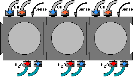
the cylinders, cooling, oil, crankshaft and camshaft as well. Increasing
the modularity of engine systems creates a greater opportunity for recycling,
rapid repair and variable engine sizing with a fixed inventory of parts.
Further as the components are improved and optimized these improvements
become simultaneously available to all parts of the system simultaneously.
