The Varifocal
Membrane Mirror
|
The Varifocal
Membrane Mirror
|
|
Human Intervention
I was thinking how it would be difficult
to assure that the images were coregistered, that is the same size and
focal length. I was thinking about how keeping a human in the loop
would make lining up consecutive images simpler [2].
Light Gathering Power
In the midst of all this I remembered an
idea I had been thinking about for a good while; A nice way to build cheap
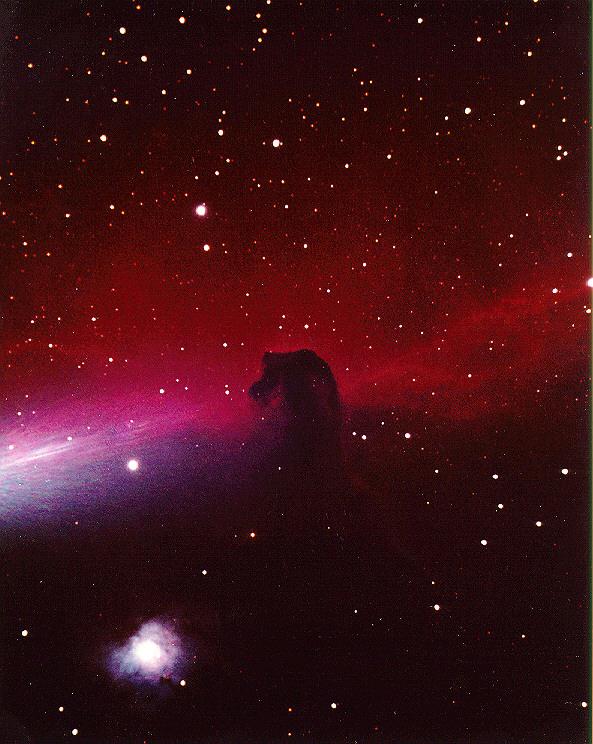
telescopes with lots of light gathering power. Light Gathering Power is
directly proportional to the area of the mirror, which in turn is proportional
to the square of the radius. A large inexpensive mirror would be a great
asset for the amateur astronomer since it would enable the viewing of a
much fainter set of objects.
![[Graphics:indexgr4.gif]](indexgr3.gif)
Angular Resolution
The cousin of LGP, resolving power is linear
proportional to the diameter of the mirror. Resolving power, also known
as Angular Resolution determines how much detail can be seen, as in the
rings of Saturn for example.
Reflections On Palomar
Several decades ago, when the 200 inch Palomar
mirror was being cast it took 8 months for the glass to cool and over 11
years of shaping in the optical shops of CalTech[4]. At 14.5 tons it was
also quite heavy[5]. A membrane mirror can be made in a few hours. A membrane
mirror could be quite light. But a membrane might not pull into a perfect
parabola. It might not pull into a sphere. I became concerned that geometric
aberation would result when the mylar surface was deformed, that uncorrectable
artifact would contaminate the resulting images, making them unuseable.
Day Tripping
On the Wednesday following our trip to the
park I stopped by a local college. In front of the chalkboard I broached
the idea to the chairman of the astronomy department, Andre Rollefson.
The chairman shared my concern that geometric aberration was a significant
concern. He reminded me that Hubble had been corrected with downstream
optics, and jogged my own recollection of those events - I had been at
JPL while the modifications to the Wide Field Planetary camera were being
made. At this moment, in my mind, the shape of the downstream corrective
element became important. Area is plentiful in a membrane mirror, a few
points of Fstop lost through corrective elements are easily recovered by
making the mirror bigger. The chairman referred me to the assistant planetarium
director Charles Hemann. Beginning with my intention of an array of telescopes
and ending with suggesting a membrane mirror I repeated the argument, this
time on a steno pad. I asked him plainly. "if spherical aberration could
be rectified after the fact." He again mentioned that this was, "apparently
what had been done on Hubble." I was buoyed up by the realization that
I could perhaps build a huge flexible film mirror and then with a downstream
optical element correct for the artifact. It was during my sketching at
this second meeting that I realized one could digitally trade field of
view for signal to noise by simply tiling or compositing the images from
an array of optical telescopes. A mock up of this idea is shown using
a conventional image [6]:
Field of View Trade: 4 Mirror Configuration
- Wide Angle Tiling of 2 x 2 Array
 |
 |
 |
 |
Experimental Procedure
Before sinking a large sum of money in an
idea, it is often useful to build an inexpensive prototype, just to establish
feasibility and to identify trouble spots.
On the following Saturday, I took a coffee
can with a hole in the bottom and attached a plumbing fitting. A three
foot length of clear 1/4" vinyl tubing tubing connected this fitting to
a 50 cc syringe. The can was filled halfway with water.
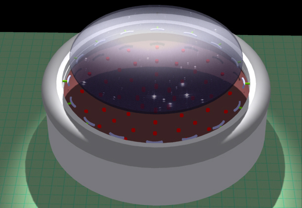
The first surface was an oven bag which
was painted in place by misting with multiple applications of chrome spray
paint.
After the painted oven bag proved unsatisfactory (the reflectance was low) aluminized mylar film was stretched over the top and securing with a series of wide rubber bands. This initial method took two people, one to hold the membrane and one to place the rubber band. The mylar was then trimmed, the wrinkles were pulled out and black gaffer's tape was used to secure the film. Black gaffer's tape is a fine fabric tape resembling duct tape, but with a higher quality, less gooey adhesive. It can be torn into strips. When the water was withdrawn using the 50cc syringe, the image appeared bright and reasonably uniform. This crude varifocal mirror began to work. It was exciting.
A week later, while making the photographs for this article, a much easier method of attaching the membrane to the lip of the can that required no rubber bands, made a much better seal and did not use the gaffer's tape.
Observations
0) Obtaining a watertight seal at both the
fitting and the drumhead was nontrivial, requiring several attempts.
1) Stretching the film uniformly over the
rim -drumhead style- was quite difficult.
2) Bright chrome spray paint is dull gray
when applied to plastic.
3) With the painted oven bag, as the vacuum
was drawn, the reflectance appeared to drop as the concavity of the mirror
increased.
4) The reflectance of the aluminized mylar
also appeared to drop slightly when the film was placed in tension.
5)The smoothness of the mirror, and uniformity
of the surface improved with time as the mirror remained in tension.
6) Significant magnfication of the ceiling
could be produced by withdrawing water and pulling the membrane down. This
was no surprise. It was the intended effect. What was surprising was how
quickly and easily the focal length of the mirror could be changed... hydraulically.
7) There were fringes of distortion from
small defects in the rim at the edge of the membrane. These are visible
in the title picture above.
8) The unit is sensitive to barometric pressure,
air and water temperature.
9) With water in the unit as the principal
working fluid, tilted operation is limited. This restriction can
be relieved by using a larger syringe or a simple vacuum pump to withdraw
a greater volume of air.
Data Collection
These are crude first-order measurements but one must start
somwhere. The first order of business was to measure
the shape of the membrane mirror to determine what kind of geometric aberration
the stretched film would prefer. A flat metal ruler laid across the top,
bisected the tensile mirror. The image of the ruler yielded a good
reflection of the shape of the mirror surface.
To reduce perspective and parallax measurement errors, a piece of Lexan served to provide fixed plane of observation. Using electronic calipers we measured the distance from the ruler to its reflection with the Lexan sheet always enforcing the constraint of constant distance. The upper edge of the Lexan sheet is barely visible in the left photograph.
Placing the zero point exactly in the center our initial measurement showed that the reflected curve was symmetric to the tolerance of our measurements, about a quarter of a millimeter. With zero representing the center of our mirror, our raw data looks like the following. All units are in mm, read directly off the electronic calipers.
![[Graphics:indexgr8.gif]](indexgr8.gif)
![[Graphics:indexgr14.gif]](indexgr14.gif)
This looks more reasonable.
Details
Now we are in a position to compare the
measured shape of our mirror to an ideal parabola. First we will define
a simple parabolic shape function with a coeffiecient we can tweak. Then
we will build a table of values that correspond to the exact x-ordinates
we measured above. Our choice of coordinate system makes the equation
for the profile of the idealized shape very simple:
Error Analysis
The measured membrane points are above and
below the ideal points to the following extents:
The error between the membrane and the ideal parabola is distributed both positively and negatively. Since the greatest error is still within the tolerance of our measurements, to first order, membrane appears close to the required shape. Typical astronomy quality mirrors are ground to a quarter to half a wavelength of light in accuracy, on the order of 200 nanometers. We are far from that level of accuracy in this, the first exploration of the idea. The results indicate that further work is justified and our three dollar prototype has served its purpose. More accurate methods of measuring the surface of the membrane will be required in subsequent attempts. But by that time we should be off the coffee can, and onto precision ground, truly circular rings.
Integrating Absolute Error Profile
To determine the best fit parabola we minimize
the total error across the face of the mirror subject to the constraint
of meeting the center and rim. Repeating the plot of the error above, but
this time with absolute value give us:
![[Graphics:indexgr22.gif]](indexgr22.gif)
![[Graphics:indexgr26.gif]](indexgr26.gif)
In the interval of x from -1 to 1 the sections appear to agree fairly closely. Let's look at the error relationship.
![[Graphics:indexgr28.gif]](indexgr28.gif)
The shape of this brief excursion error relationship is not the same as our measured example, so this refined attempt at explaining the error profile is not applicable at this crude level of measurement. Improved Ring Specification
Conclusions
Two models of the membrane mirror were built and
demonstrated. Initial measurements were taken and an analysis methodology
was developed and presented. Significant refinements in both construction
and measuring techniques will have to be applied. This simple proof of
concept
demonstration implies that the idea is worth pursuing further to the next
level of refinement with precision metal rings for membrane suspension.
It
has been suggested by Charles Rydel of Paris France that concentric high
voltage electrodes could be used to improve the shape of the membrane.
I propose extending
this further by adding a radially symmetric set of point electrodes to give
precise control of shape, as illustrated below. The applied voltages could
be controlled by a DSP chip and closed loop feedback system to produce
a time
averaged mirror of useable shape.
 |
Other Questions
For a General Introduction see Ultimate Beginners Guide to Astronomy
References
[1] Yaeger, Larry and
Upson, Craig "Combining Physical and Visual Simulation - Creation of the
Planet Jupiter for the Film 2010", Computer Graphics, Volume 20,
Number 4, 1986, pps 85 - 93. esp p 86 Section 3 Paragraph 2.
[2] Views
of the Earth
Summary: The images used were taken
by CZCS (Coastal Zone Color Scanner) of NASA Nimbus
7 satellite. The images used
were taken by the NOAA weather satellites and knitted together by artist
Tom Van Sant and computer graphicist
Lloyd Van Warren for The Geosphere
project
[3] Various types of optical telescopes including Newtonian, Prime Focus, Cassegrain and Coude´
[4] The
Palomar Observatory
Summary: Part 1 Part 2 Part 3 Part
4. FORWARD BACK HOME The Pyrex mirror was cast at
the Corning Glass Works in
New York in 1934. It took more than 11 years in the optical shops at
Caltech to figure the raw
piece of glass into the perfect surface it is today.
[5] Palomar
Observatory: Visitor Brochure
Summary: Even more significant
is the development of new electronic devices that sense faint signals
of light from distant celestial
objects. One of the reasons Palomar Mountain was selected as the site
for the 200-inch telescope
was its dark skies that would allow observation of the faintest galaxies
without the interference of
city lights.
[6] Astronomy
(Science)
Summary: Ben's Space Pages -- Linking
Hyper Space to Outer Space. Space
Telescope Electronic Information
System (Gopher).
[7] MATH
1509AC --- PROJECT 1
Summary: Namely, all light rays
parallel to the symmetry axis are reflected to pass a single focal
point. (i) All light rays parallel
to the symmetry axis of a parabolic mirror are reflected through a single
focus; (i) A spherical cap does
not bring light rays parallel to the symmetry axis to a single focus.
[8] Aluminised
Mylar as a Flux Collector
Summary: Aluminised Mylar as a
Flux CollectorThe telescope was first shown at an August 5, 1978, exhibition
meeting of the Southeast Group of Astronomical Societies, and again on August
26-27 at the Epsom Borough Show, in the booth of the Ewell Astronomical Society
(Maurice Gavin - Worcester Park - Surrey - England vice-chairman).
![[Graphics:indexgr6.gif]](indexgr6.gif)
![[Graphics:indexgr12.gif]](indexgr12.gif)
![[Graphics:indexgr13.gif]](indexgr13.gif)
![[Graphics:indexgr16.gif]](indexgr16.gif)
![[Graphics:indexgr18.gif]](indexgr18.gif)
![[Graphics:indexgr20.gif]](indexgr20.gif)
![[Graphics:indexgr24.gif]](indexgr24.gif)
![[Graphics:indexgr25.gif]](indexgr25.gif)
![[Graphics:indexgr27.gif]](indexgr27.gif)