Written by: David W. Ishmael WA6VVL 2222 Sycamore Avenue Tustin CA 92780 (714) 573-0901 daveishmael@cox.net home email dave_ishmael@qscaudio.com work email
Latest Revision: 29 August 2009
Judging by the activity on eBay and both my snail mail and e-mail requests for information during the last seventeen years, the continuing popularity of the Knight Kit Ocean Hopper just never ceases to amaze me. It seems that a lot of us cut our teeth on this little regenerative receiver.
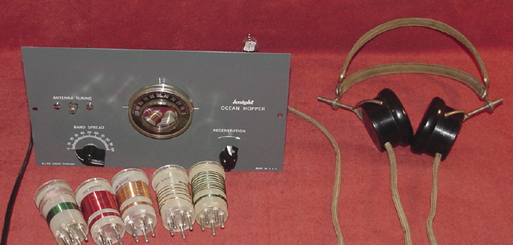
Front View of a Model 749 Knight Kit Ocean Hopper circa 67 shown with its 5 optional coils and high-sensitivity Baldwin Type C headphones. The front panel is original and the plastic 0-100 main tuning dial is in unusually good condition.
The last generation of the Knight Kit Ocean Hopper (OH), and the subject of this webpage, was released in late 53 and appeared for the first time in the 54 Allied Radio catalog. It was sold for 14 years, last appearing in the 67 catalog, and was closeout priced at $18.88 in a May 67 flyer which included the five optional coils and headset. The last generation OH featured a 12AT6 regenerative-detector, a 50C5 audio amplifier, and a 35W4 half-wave rectifier, all 7-pin miniature tubes. The frequency coverage was 155-470 KHz (54 to 59) or 165-540 KHz (60 to 67 the long-wave coils frequency range was increased to 165-540 KHz to cover the 500 KHz International distress frequency for ships at sea) and 530 KHz to 35 MHz using a total of six 5-pin plug-in coils. The 530-1900 KHz Broadcast Band coil came with the kit, the other 5 were optional. An optional cabinet became available in 57 and by the Winter of 58 it was included with the kit. The OH is powered off of the 120 Vac line and the chassis is hot one side of the line is connected to the chassis through a 0.05 uf/270K parallel RC network. The design is simple and straight-forward and after restoring/rebuilding several dozen of them during the last fifteen plus years I have yet to find one that doesnt work.
If you are fortunate enough to find an OH in original condition, the Achilles heel is the 3-section filter capacitor it will be open. The original filter capacitor was 30/30 uf @ 150 Vdc and 20uf @ 25 Vdc and has the Allied Radio P/N 213301 printed on it. Fortunately, a satisfactory replacement is available from Antique Electronics Supply, their P/N C-ER33-47-22, a 33/47 uf @ 160 Vdc and 22 uf @ 25 Vdc. You can also use three individual capacitors and use the original mounting hole to install a terminal strip. Since these are entry-level kits and in many cases represent our first attempt at kit building, the quality of the wiring ranges from pristine to mediocre to horrible. Typically, there are three categories that I put OHs into. The overall condition is:
In all three categories, the condition of the steel chassis can also vary from pristine to completely rusted out - the plating used on the OHs chassis does not appear to be very robust and more times than not is responsible for the biggest single deficit in the cosmetic appearance of an OH next to the front panel. I have successfully used the following procedure in rebuilding a dozen or so OHs in the third category (OK w/acceptable wiring). This procedure, like the OH, is relatively simple, straight-forward, inexpensive, and can breath new life into an OH.

Steel chassis from a Model 740 Ocean Hopper notice the extra hole for the filter choke leads. There are still some spots of corrosion visible so it will need a second treatment. Changing to a coarser grade of wet/dry sandpaper might also be required if the corrosion is deep enough. In terms of overall cosmetic appearance, I think I would prefer using a finer-grade wet/dry sandpaper and more "elbow-grease" to minimize the visible line-graining. Also, keep in mind that even a "Brillo Pad" or "S.O.S. Pad" will result in very fine lines on the finished chassis.
At this point, the OH is finished and ready for testing. The above steps typically take me a total of 2-4 hours depending upon the condition of the chassis. If I coat it with Krylon Crystal Clear Acrylic I let it dry overnight before reassembling it or if its a warm sunny day, Ill put it outside for several hours in the sun. All of the OHs I have owned, restored, and rebuilt, have worked pretty much the same. Thats not to say that they havent had some individual idiosyncrasies. Like any regenerative-detector, selecting a 12AT6 for maximum gain and regenerative characteristics is time well spent. Improvements in the audio gain can also be achieved by selecting 50C5s. Remember, using the original OH components, the gain from the antenna to the headphones is absolutely dictated by the tubes and there are considerable variations in gain from tube-to-tube, both as a detector and audio amplifier. Also, a tube checker will not be useful in determining detector gain and regen characteristics it has to be done in the OH.
Depending on the original condition of the chassis, the results of your 2-4 hours of work in terms of before/after differences can be SPECTACULAR!!
WARNING and Comments on the Ocean Hoppers Hot Chassis Please Read
Over the years, I have received literally dozens of letters and emails regarding my decision to use the original primary wiring and a polarized cordset in the rebuilding the Allied Radio Knight Kit Ocean Hopper and Space Spanner. Words like "deathtrap" and phrases similar to "you're going to kill someone" were common. I have shared and discussed these letters and emails at length with Ray Osterwald, N0DMS, the owner/editor of Electric Radio Magazine, especially after my 1954 Ocean Hopper (ER#184, Sep.04), Space Spanner (ER#193, Jun.05), and 1946 Ocean Hopper (ER#200, Jan.06) articles were published. Let's look at the issues with the 1954 Ocean Hopper:
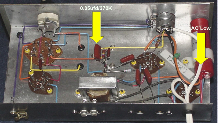
This is a view of the wiring of my recently rebuilt Model 740 Ocean Hopper circa '57 w/original wiring. Note the position of the 0.05 ufd/270K parallel RC-network between the switched AC low and chassis ground.
Some additional comments might be useful in putting the above into some perspective:
Finally, it might be useful to repeat the warning found in the Ocean Hopper's manual: CAUTION: NEVER TOUCH ANY PART OF THE WIRING WHILE THIS RECEIVER IS PLUGGED INTO A POWER OUTLET. NEVER USE OR TEST THE OCEAN HOPPER ON OR NEAR A GROUNDED METAL BENCH, RADIATOR, SINK OR OTHER GROUNDED METAL OBJECT. SERIOUS BODILY INJURY OR PROPERTY DAMAGE MAY RESULT IF THIS WARNING IS NOT HEEDED.
If you're going to use a 115 Vac to 115 Vac isolation transformer, I prefer the upright-mounting enclosed-type with an AC connector or AC power cord over the open-frame type with exposed/flying leads. Also, many of the upright-mounting enclosed-types also have exposed/flying leads and require an enclosure of some type. Some of the isolation transformers that I would recommend in the 100 to 150 VA class include:
Comments on Completely Rebuilding Your Ocean Hopper:
If you decide to completely rebuild your Ocean Hopper, by far the most labor-intensive and tedious part of the rebuild is preparing the original components for the rebuild. I can't overstress the value of PATIENCE. Replacement 7-pin wafer tube sockets with 1-5/16" mtg. ctrs. are becoming "unobtanium", so every effort should be made not to damage them or break a pin, and I cant caution you enough in handling them with kid gloves. Ditto the 5-pin wafer socket and the speaker and headphone connectors.
Some more random thoughts:

Rear view of my rebuilt Model 749 Ocean Hopper circa 59. This version still uses the filter choke. The fine-lines from the wet/dry sanding process are just visible and I used a circular pattern in finishing the sanding. Several coats of Krylon Crystal Clear Acrylic have been applied. The front panel and tubes are original. The tube line-up viewed left-to-right is 35W4 rectifier, 50C5 audio amplifier, and 12AT6 regenerative detector. The coil is the standard 530-1900 KHz broadcast band P/N 111204.

Rear view of another rebuilt Model 749 circa 66. The tubes are the original Knight-branded RCA. The lines are a bit more visible because a coarser grade of wet/dry sandpaper was used. Several coats of Krylon Crystal Clear Acrylic have been applied. The front panel is a reproduction and the wiring and tubes are original.

Rear view of another rebuilt Model 749. The chassis of this OH was very badly corroded and rusted so after cleaning it up with a wire brush and ¼" drill, the chassis had several coats of Krylon Crystal Clear Acrylic applied. If you look closely, the chassis is heavily "line-grained" because of using that wire brush, but I thought it was cosmetically acceptable. Your tastes may be different. The front panel and Knight-branded RCA tubes are original but this OH was completely rewired. This Ocean Hopper was rebuilt in Apr.92 and was the first OH I had owned since I built mine as a teenager in 59. In reviewing the photos I took of this particular rebuild, I think I could have used a slightly coarser grade of wet/dry sandpaper without getting so aggressive with the wire brush. Incidently, I sold this rebuilt OH almost ten years later, and the Krylon Crystal Clear Acrylic coating held up extremely well.

Rear view of a rebuilt Model 740 circa '57 with an original filter choke installed. The fine-lines from the wet/dry sanding process are just visible. Several coats of Krylon Crystal Clear Acrylic have been applied. The front panel is a reproduction and the unit was completely rewired by a previous owner.

Rear view of a recently rebuilt Model 740 circa '57 with a Stancor P/N C-1707 filter choke installed. The original chassis was pretty rusty so it was cleaned top and bottom with a wire brush in a drill press, followed with an electric sander, followed with several coats of Krylon Crystal Clear Acrylic. The frames of the tuning capacitor, filter choke, and audio output xfmr were also cleaned using the wire brush in the drill press. The front panel is a relatively rare 3rd-generation without the cabinet mtg. holes that was released in '57 just prior to Allied making the optional cabinet available and adding the two mtg. holes to the front panel. This unit was completely rebuilt and rewired, and the 12AT6 and 50C5 tubes selected for maximum performance.

Rear view of another rebuilt Model 740 circa '58 with an original filter choke installed. The tubes are the original Mullard. The chassis of this OH was very badly corroded and rusted so after cleaning it up with a wire brush and ¼" drill, the chassis was painted with several coats of primer, top and bottom. The tubes and front panel are original. The Allied Radio Winter '58 Supplement marked the transition from the Model "740" to Model "749".

This is another rebuilt Model 740 Ocean Hopper and is a bit "unique" because it has been converted to octal tubes. The chassis of this OH was very badly corroded and rusted so after cleaning it up with a wire brush and ¼" drill, the chassis was painted with several coats of primer, top and bottom. The tube line-up left-to-right is 45Z5 rectifier, 35L6 audio amplifier, and 12SR7 regenerative detector. The performance of the octal version is identical to that of the 7-pin miniature version. This unit has been completely rebuilt and features a front panel made from 0.062" aluminum. In spite of being a "forgery", this is my favorite Ocean Hopper.

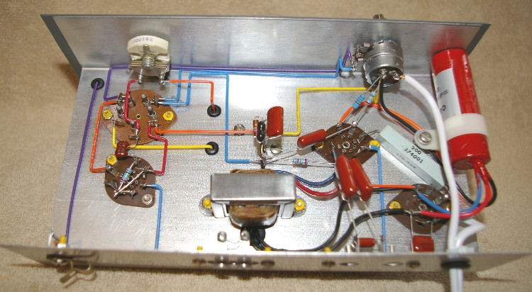
This is a view of the wiring of my Model 749 Ocean Hopper circa '59. The filter capacitor is from Antique Electronics Supply, their P/N C-ER33-47-22 , held in place with a 7/8 I.D. nylon cable clamp Waldom P/N CCN-42 or equiv., and the line cord has been replaced with a polarized 2-wire Radio Shack P/N 61-2852 6' line cord. The wiring is 20 gauge solid wire using the colors specified in the assembly instructions. The tube sockets, speaker and headphone connectors, white tubular capacitors, output transformer, regeneration control, and bandspread capacitor are original. This is the most authentic rebuild of all the Ocean Hoppers I have rebuilt in 15+ years.

This is a view of the wiring of my recently rebuilt Model 740 Ocean Hopper circa '57. The filter capacitor is from Antique Electronics Supply, their P/N C-ER33-47-22 , held in place with a 7/8 I.D. nylon cable clamp Waldom P/N CCN-42 or equiv., and the line cord has been replaced with a white polarized 2-wire cordset. The wiring is 20 gauge solid wire using the colors specified in the assembly instructions and I used right-angles where possible. Compare the "look" of this one to the one above. Which do you prefer??? The tube sockets, speaker and headphone connectors, output transformer, regeneration control, and bandspread capacitor are original. This particular Ocean Hopper had already been rebuilt when I received it, so the original capacitors were long gone. As a result, I decided to use the same series "modern" film capacitors throughout 6 total (2 hidden in this view). This is the 3rd time this Ocean Hopper has been built!!!
This is a view of the wiring of my recently rebuilt Model 749 Ocean Hopper circa '61 that I finished in Aug.09. This is nearly identical to the one above. I added a 6-32 x 3/8 spacer to lift the filter capacitor so that I could use the short leads of the original 200 ohm 10W resistor

Of course, if you get "desperate", you can start from "scratch" and rebuild the entire Ocean Hopper. This is a Model 749 reduced to "kit form" in Jun.'07. The front panel is original. The chassis of this OH was lightly cleaned with wet/dry sandpaper and several coats of Krylon Crystal Clear Acrylic applied. Start-to-finish, rebuilding an Ocean Hopper from "kit form", which includes the tear-down and prepping the chassis and parts for the rebuild, will take a full day.

A close-up of my rebuilt Model 749 Ocean Hopper with a relatively pristine original front panel. The plastic 0-100 main tuning dial is in unusually good condition it's crystal clear - many of these plastic main tuning dials turn yellow as they age.
Selected References:
Ocean Hopper Coil Data:

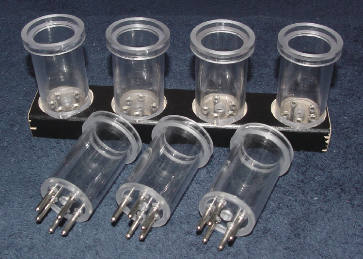
Finding original 1-1/4 dia. x 2-1/4 high 5-pin rimmed-type coil forms (manufactured by the American Phenolic Corp., Cat. No. 24-5P) can be challenging at best. Fortunately, the coil forms pictured below can be obtained from Larry Baker, WB5OFD. His coil forms are high-quality, hand-made, and are visually near-identical to the originals. Keep Larry in mind if you need to wind your own coils for your Ocean Hopper or just want to experiment with different frequency ranges.
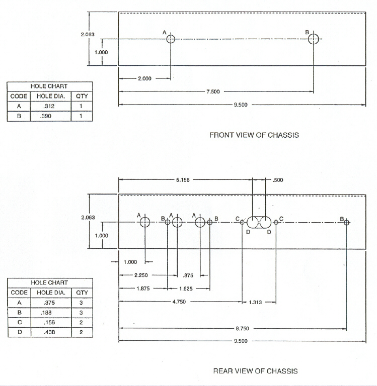
Mechanical Drawings:


Model 749 Ocean Hopper Schematic:

Model 749 Ocean Hopper Wiring:

Model 749 Ocean Hopper Bill of Material (BOM):


