Distributed Load Problem
Problem: A simply supported beam is subjected to a distributed load that varies linearly along its span. The expression for the distributed load is:

Determine the reactions at each of the supports, the deflection along the span, the slope at the endpoints, the shear and the bending moment.
Solution:
L = beam length
RA = the reaction at support A
RB = the reaction at support B
wm = slope of spanwise load function
wb = intercept of spanwise load function.
y(x) = deflection as a function of x.
V(x) = shear as a function of x.
M(x) = bending moment as a function of x.
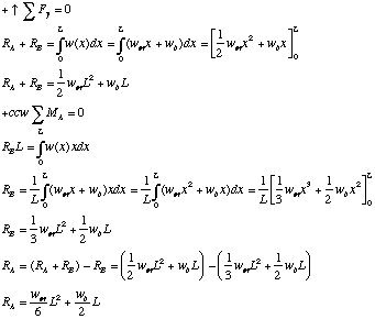
We will solve the problem in two parts. First we sum forces and moments to deduce the values of the reactions at supports A and B. Then we will produce expressions to describe the deflection, shear and bending moments.


Now we need to plug in the boundary condition to find the value of C1:

Which gives us a complete result for shear. Now we proceed with bending moment:

Which gives us a complete
result for bending.
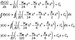
To compute spanwise deflection and slope we must refer to linear bending theory
which (under the assumption of constant stiffness) gives us that:

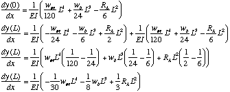
Having completed this integration we can now evaluate both remaining constants by inserting the boundary conditions:

With this behind us we can generate complete expressions for the deflection and slope:

Our only remaining errand is to evaluate the slope expression at the endpoints:

and to remember that end slopes are in radians.
Example Problem 1:
We first run a BeamCALCulator that only handles a uniform load:
Load Parameters
Load wm: 0; Slope of spanwise
load function
Load wb: 10 lbs/in; Uniform Load
Length: 36 in;
Material Parameters
Material: Aluminum 6061
T-6
Elastic Modulus: 10,100,000 psi
Yield Strength: 35,000 psi (Tensile)
Density: 0.098 pci
Cross Sectional Parameters
Outer Width W: 1.00 inches
Inner Width w: 0.85 inches
Outer Height H: 1.00 inches
Inner Height h: 0.85 inches
Example Problem 2:
We then run a BeamCALCulator that handles a linearly varying load with the uniform load case and compare the results:
Load Parameters
Load wm: 0; Slope of spanwise
load function
Load wb: 10 lbs/in; Uniform Load
Length: 36 in;
Material Parameters
Material: Aluminum 6061
T-6
Elastic Modulus: 10,100,000 psi
Yield Strength: 35,000 psi (Tensile)
Density: 0.098 pci
Cross Sectional Parameters
Outer Width W: 1.00 inches
Inner Width w: 0.85 inches
Outer Height H: 1.00 inches
Inner Height h: 0.85 inches
Example Problem 3:
We then run a BeamCALCulator that handles a linearly varying load with a tapered load case whose end support reactions are the same and compare the results:
Load Parameters
Load wm: -720/L2=.56 lbs/in2
Slope of spanwise load function
Load wb: 20 lbs/in; Uniform Load
Length: 36 in;
Material Parameters
Material: Aluminum 6061
T-6
Elastic Modulus: 10,100,000 psi
Yield Strength: 35,000 psi (Tensile)
Density: 0.098 pci
Cross Sectional Parameters
Outer Width W: 1.00 inches
Inner Width w: 0.85 inches
Outer Height H: 1.00 inches
Inner Height h: 0.85 inches